



Failure Analysis on load cell
The object
A load cell is an electronic device used to measure the force or load applied to it. It consists of a stress-sensitive structure, usually made of a metal alloy or ceramic material, that reacts by deforming when a load is applied. This deformation is converted into an electrical signal proportional to the force applied.
Load cells are used in a wide range of applications, such as in industrial and commercial scales to measure the weight of objects, in machinery to monitor tension or pressure, in vehicles to measure axle loads, or in structures such as bridges and cranes to monitor load and prevent overloading.
Possible failure modes of a load cell may include:
- Overload | applying a load exceeding the maximum capacity of the load cell can cause irreversible damage to the structure, impairing its accuracy or even causing it to break.
- Underload | if the applied load is less than the minimum sensitivity of the load cell, it may not be able to detect the weight correctly or provide an accurate measurement.
- Permanent deformation | If a load cell is subjected to loads beyond its elastic limit, it may undergo permanent deformation that will affect its accuracy and reliability.
- Mechanical wear | prolonged and repeated use of a load cell can cause mechanical wear on internal components, leading to deterioration in performance over time.
- Manufacturing defects | design errors or problems in the production of the load cell can lead to structural defects or malfunctions that affect its accuracy and durability.
To maintain the accuracy and safety of load cells, it is important to follow the manufacturer’s technical specifications, use them within the recommended load limits, and maintain them properly.
Purpose of the survey
The Customer has requested a failure analysis on the load cell from the laboratory . The objective is to assess the possible causes of component failure during its use. The load cell was located under a weighing bar, which in turn was located under truck weighing bridges.
During use, the load cell was being crushed by the load on the weighing bridges and weighing bar, in a load condition similar to a hinged shelf with a concentrated force.
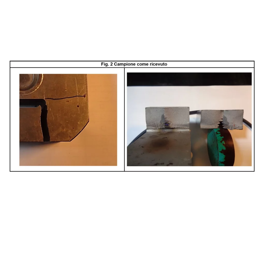
The Principal reports that the component broke about a year and a half after it was put into service and reports that other components have also suffered similar failures. The component failure occurred from radius R2.5 and propagated through the entire thickness of the part, partially involving the threaded hole.
According to the information provided by the Client, the load cell was fabricated from quenched and tempered alloy steel of type 40CrNiMoA, complying with GB/T 3077-2015. The material was supplied in the quenched and tempered and machined state.
The analyses
The load cell fracture occurred in the area of the upper R2.5 radius, partially affecting the thread.
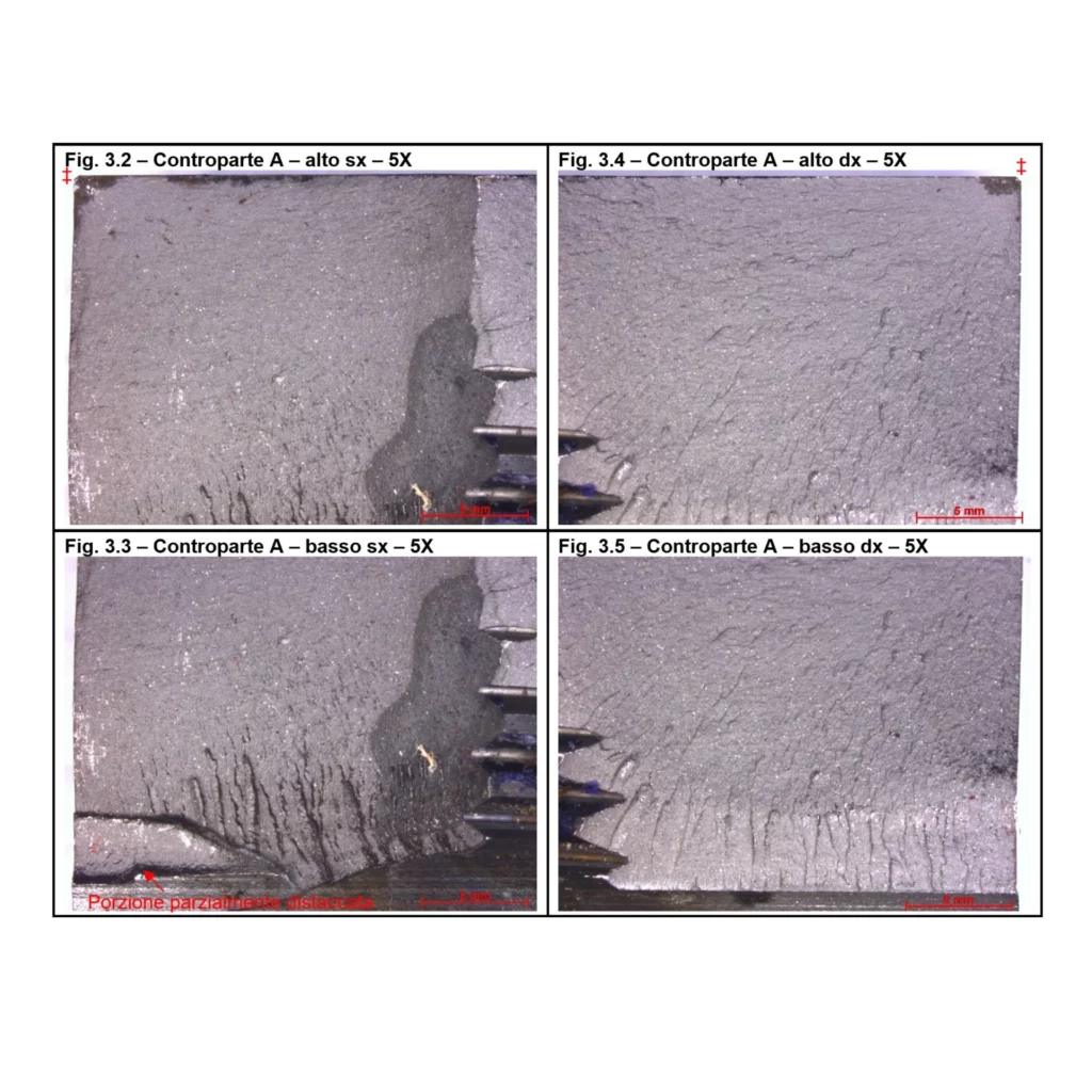
The fracture surfaces have a dull, light gray appearance, with parallel grooves and presence of corrosion at the outer edges. We hypothesize a brittle overload fracture, triggered by the outer edges and influenced by a possible corrosive process. The fracture propagated to the resistant section of the component.
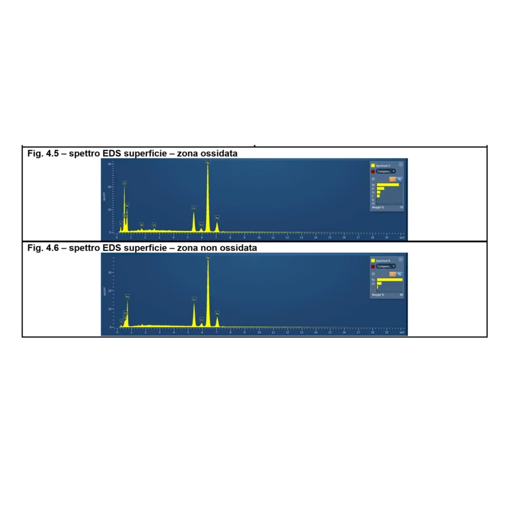
Morphological analysis by scanning electron microscope (SEM) and elemental analysis by EDS probe were conducted on counterpart A of the load cell.
Fractographic and morphological features were similar to the specular counterpart. Mixed fracture morphologies, both intergranular and transgranular, were observed in the outer fracture zones near the edges and in the lower part of the section.
EDS probe analysis revealed a chemical composition with predominance of iron, oxygen, chromium and carbon, and traces of silicon and chlorine. The presence of oxidation and increased oxygen content in the oxidized zone confirm the presence of corrosive phenomena. The chemical composition is associated with a stainless steel with a high chromium content, unlike what was originally expected (quenched and tempered alloy steel).
Fractographic observation suggests that the component broke due to overloading in the brittle fracture regime. No inclusions or other metallurgical defects were observed, except for the areas affected by corrosion.
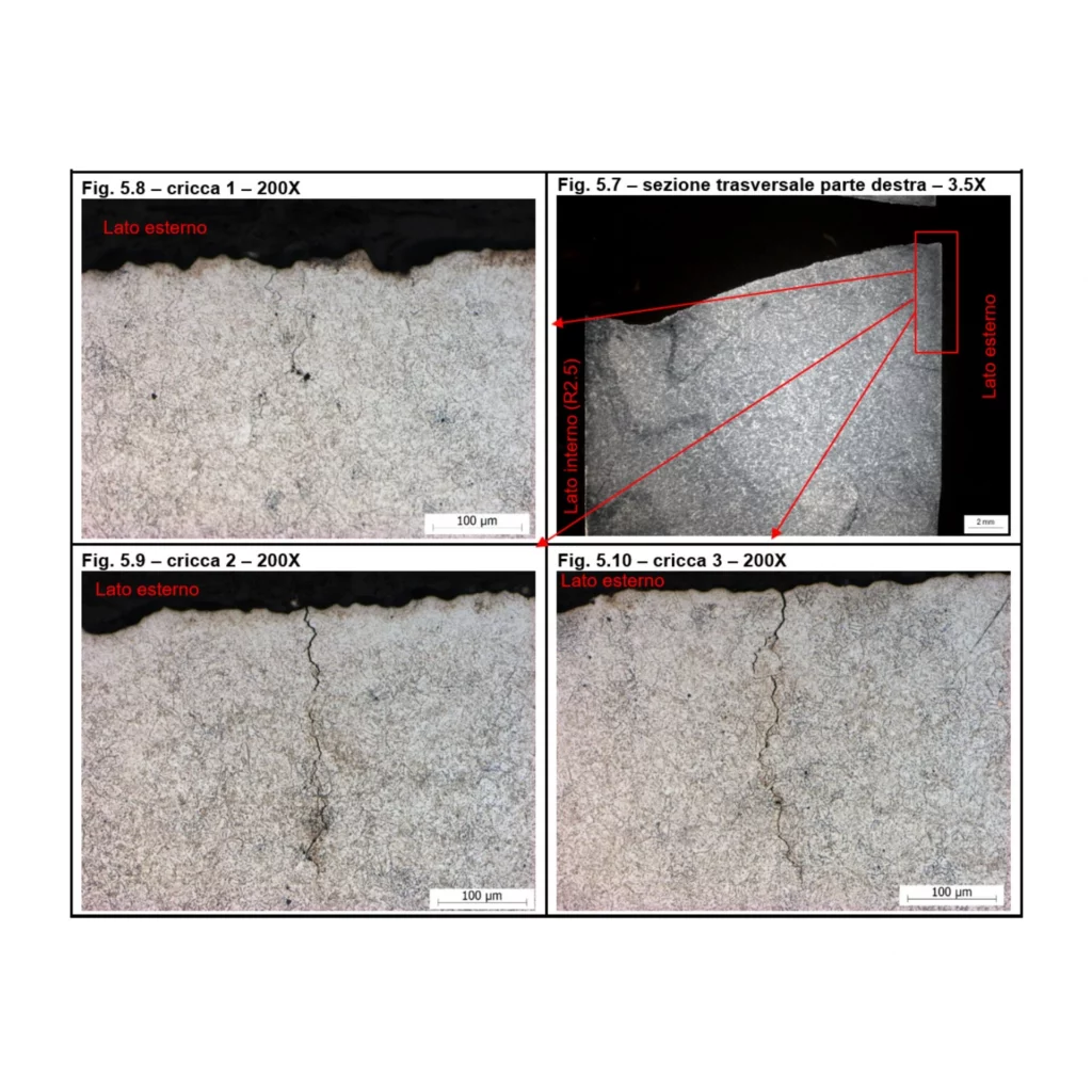
Micrographic analysis of the fracture surface was conducted on two distinct areas to the left and right of the threaded hole, intercepting the areas affected by corrosion on the outer edges. Both fracture surface profiles exhibited a jagged appearance along the short traverse of the component, with a less jagged profile on the inside of the left side. No areas of crushing or recutting were observed along the fracture surface.
The fracture had a mixed pattern, both intergranular and transgranular, consistent with previous observations. Several intergranular cracks were identified on the outer side not involved in the fracture, probably associated with localized forms of corrosion.
The microstructural features observed are similar to those previously analyzed. In general, the fractographic evidence confirms what has been observed in previous analyses, and no metallurgical anomalies or discontinuities were found in the fracture zone, except for the areas affected by localized corrosion.
Material analysis revealed that the component consists of a martensitic stainless steel of type AISI 420 or X30Cr13. This classification is in contrast to the information provided by the Client regarding a 40NiCrMoA quenched and tempered alloy steel. Micrographic examination confirmed the presence of distended martensite and dispersed fine carbides in the microstructure of the material, indicating hardening and stress relieving heat treatment. No discontinuities or microstructural anomalies were detected.
Tensile and resilience tests performed on the load cell showed results that differed from UNI EN 10088-3:2014 specifications for the +QT850 delivery condition.
ASTM A276-13a does not provide minimum values for the mechanical tensile or resilience properties of AISI 420 steel.
The Rockwell hardness test found a core hardness of the load cell material between 48.5 and 49.0 HRC, which is close to the minimum hardness required by the A276-13a standard for quenched and tempered AISI 420 steel.
UNI EN 10088-3:2014 does not specify minimum hardness values for X30Cr13 steel.





The results
Based on the evidence collected and information on the use of the component, it is hypothesized that the failure was due to mechanical overload under flexural loading. No discontinuities or metallurgical defects were found, except for the outer edges with signs of corrosion, indicating local corrosive phenomena during use.
Failure is assumed to have started from the outer edges of the component, where the greatest stress intensification factor is present due to the geometry and direction of loading, along with signs of localized corrosion that may have generated and propagated defects.
The rupture propagated to the R2.5 radius zone, occurring as a crash rupture.
Conclusions
Material characterization revealed that the component is made of AISI 420 or X30Cr13 martensitic stainless steel, in contrast to the information provided by the Contractor regarding 40NiCrMoA quenched and tempered alloy steel.
The material was supplied under hardening and stress-relieving conditions, with high strength and hardness, but also inherent brittleness as indicated by the resilience and tensile test.
This brittleness, together with low resistance to localized corrosion phenomena, contributed to the component’s damage and fracture, as confirmed by the fracture surface.
Is your component damaged? Let’s find out together why
Request information