


Quality Control of Electronic Assemblies according to the IPC-A-610 standard
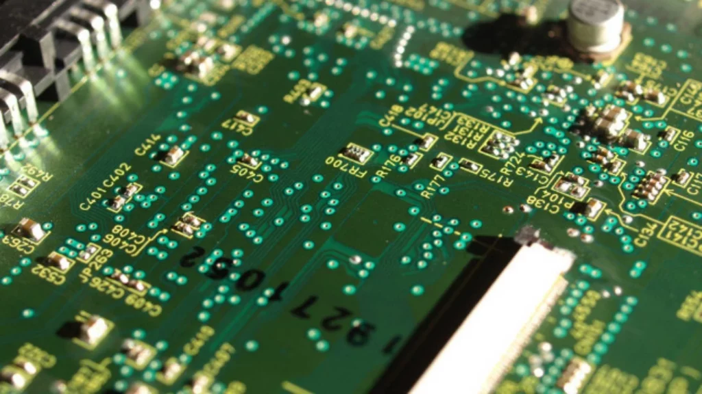
The electronic assemblies quality control service provided by the Test Engineering department is configured as a systematic multi-step process, which is essential to validate the conformity of products to the most stringent technical specifications. The mainstay of this activity is the IPC-A-610 standard, the global reference for electronic board assembly acceptability criteria(PCBA).
The acceptability criteria and IPC Classes.
The ipc standard at 610 is divided into classes, which define the criteria for acceptability of electronic assemblies. Not all PCBAs require the same level of reliability; in fact, this varies according to the intended use of the product. Determining the class to which it belongs is the first step in establishing defect tolerance limits and inspection severities. Each electronic component is evaluated by comparing its parameters with the criteria defined by the standard, according to its class of membership.
The classes provided by the ipc at 610 are:
- Class 1 – General electronic products: devices in which circuit operation is the only necessary element and aesthetic imperfection is unimportant. These are typically low-cost consumer electronics with a limited life cycle.
- Class 2-Industrial and professional products: equipment for which continuity of service and long service life is required. Examples are servers, industrial instrumentation and communication systems
- Class 3 – High reliability products for critical industries: this class represents the highest level of quality for markets such as aerospace, defense, and medical. In these areas, downtime or malfunction is not permissible because it could compromise human safety or the integrity of critical missions. Here the acceptability criteria for quality control electronic assemblies are extremely strict.
What we check: the parameters of PCBA inspection
The inspection activity conducted by the Test Engineering department is not limited to superficial verification, but consists of a granular technical analysis of each individual element that makes up the board. Each parameter is compared with IPC-A-610 acceptability tables to ensure the repeatability and objectivity of the inspection.
Electronic assembly quality control focuses on the following critical points:
- Solder quality (THT and SMD): verification of wetting, solder meniscus and metallized hole filling for Through-Hole Technology components, as well as proper joint formation for Surface Mount Device components.
- Markings and traceability: checking the legibility and correctness of labels, part numbers, and screen printing markings, which are essential for product life cycle management.
- Positioning and orientation: ascertaining correct polarity of active and passive components, verifying centering on pads, and absence of rotation or tombstoning defects.
- Mechanical and electrical integrity: inspection for soundness of fasteners, proper crimping of terminals, and conformity of wiring and internal wiring.
- Laminate condition and coatings: analysis of FR4 substrate to exclude delaminations, bubbles or burns, and check for uniformity of protective coatings (conformal coating) and weld masks.
- Absence of critical defects: systematic search for anomalies such as solder bridges (short circuits), cold solder, tin balls (solder balls), or the presence of excessive voids in the joints, which could affect the long-term reliability of the PCBA.
Inspection technologies: from AOI to X-rays
X-Ray Inspection (X-RAY)
Electrical Testing (ICT and Functional Testing)
First Article Inspection (FAI)
Thermomechanical Analysis and Standardization
Consistent application of the IPC-A-610 standard ensures quality consistency and dramatically reduces the error rate. In addition, thermomechanical analysis prevents early failures by analyzing the joints’ resistance to thermal cycling and mechanical stress, ensuring the long-term reliability of the final product.

Contact our technical team to establish a quality control plan that complies with the IPC-A-610 standard
IPC-A-610 test with TEC Eurolab
FAQ - IPC-A-610 Standard
What is the IPC-A-610 standard and why is it important?
IPC-A-610, entitled “Acceptability of Electronic Assemblies,” is the most widely used international standard in the electronics industry for visual inspection of assembled boards. It is critical because it establishes objective, measurable visual criteria (target, acceptable, defect) for every aspect of PCBA, ensuring that manufacturer and end customer speak the same quality and technical language.
What is the main difference between Class 2 and Class 3 IPC?
When is X-ray inspection required on PCBAs?
Can IPC-A-610 quality control reduce production costs?
What are the most common welding defects found during inspection?
Among the most frequent defects are:
- Solder bridges: short circuits between adjacent pads.
- Cold or inadequate welds: dull or incompletely wetted joints that impair conductivity.
- Tombstoning: lifting one end of an SMD component.
- Excess tin balls (solder balls): small residues that can migrate and cause short circuits over time.
- Misaligned or inverted components: pick-and-place errors that do not meet IPC tolerances.