
Failure Analysis on rubber hose
The object
The purpose of the following investigations is to define the causes that caused the damage on the sample “Used and hardened pipe,” provided by the customer. To conduct the analysis, the used sample was compared with a new part. The samples as arrived are shown in Figure 1.
Information provided by the client
- The developer provided the data sheet for the pipe.
- The tube is used with gasoline or gasoline solution with 20% ethyl alcohol.
- The complaints come from the European area (UK, Austria, Germany) and work in the private sector (not in roadside distributors).
- There is no knowledge of the type of gasoline that was delivered through the hose.


The analyses
The analyses performed to determine the causes of pipe rupture are:
- Microscopic observations with SEM and macrographic observations
- FT-IR Spectrophotometry
- Thermogravimetric analysis (TGA)
- Thermal analysis (DSC)
- Shore hardness A
- Fluid resistance
1. Observations of the damaged part
The damaged part was subjected to both scanning electron microscope (SEM) microscopic observations and macrographic observations. The macrographic observations show the presence of integrity defects (cracks), only on the outer layer of the tube. Specifically, these cracks are mainly arranged perpendicular to the direction of bending stress to which the tube is subjected and are concentrated on the outer, concave side of the specimen (Figure 2).
As for SEM micrographic observations, they were performed on both the outer and inner side of the incriminated tube and confirm that integrity defects are only present on the outer and concave side of the specimen, while the inner side is intact (Figure 3). In addition, it is noteworthy that during the sampling operations of the different portions, on the damaged hose, a significant stiffening of the rubber layers and less adhesion between the outer and inner layers can be appreciated at the fiber fabric.
Note: These hoses are multilayer, consisting of an inner rubber layer; a polyester or nylon fiber layer; and an outer rubber layer. The process of obtaining the hose in question is called gumming. The inner rubber layer consists of an elastomer that is resistant to the fluid passing through the hose; while the outer rubber layer will have to be more resistant to atmospheric conditions, such as: ozone, humidity, outside temperature, oxygen, radiation, etc. Therefore, in general, the outer layer is composed of a blend of two types of rubbers.


2. FT-IR spectrophotometry
A portion of both tubes was subjected to FT-IR spectrophotometric analysis using the attenuated total reflectance technique (ATR). The analyses were performed on the samples as arrived, after extraction in organic solvent and on the liquid fractions obtained from the extraction of the tubes with the solvent mixture. The FT-IR spectra obtained are shown in Figures 4 and 5.
By comparison with the available spectra libraries, the FT-IR spectrum of both samples (after organic solvent extraction) is mainly correlated with a nitrile rubber (NBR) (Figures 6 and 7).
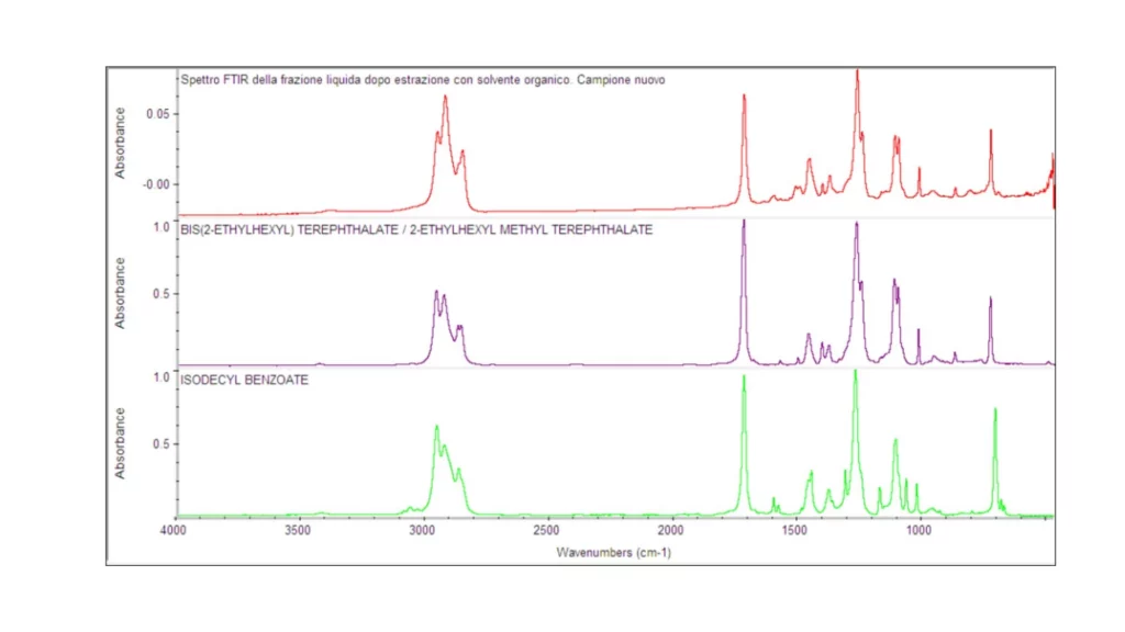
As for the liquid fractions, obtained after 12 h of extraction in organic solvent, they can be traced to polyester-based compounds, which are used as plasticizers in elastomeric compounds (Figure 8).
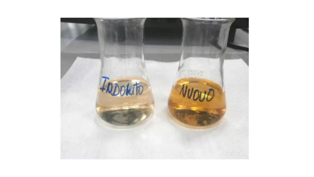
In addition, it is noteworthy that from the superposition of the spectra, particularly in the fingerprint area of the spectrum, differences are observed between the absorption peaks constituting the FT-IR spectra of the aforementioned liquid fractions. This difference can also be appreciated by the different coloration of the liquid fractions analyzed (Figure 9).
Note: Organic solvent extraction allows separation of the fraction of volatile and semi-volatile (low molecular weight) compounds. This fraction is very important in the rubber article because it represents all the additives of an organic nature. These substances are those whose function is to sacrifice themselves so that the polymer does not degrade. The qualitative and quantitative determination of this fraction is not easy, as they are substances that are lost over time and are kept secret by suppliers of elastomeric compounds. Ingredients belonging to this fraction are for example:
- Plasticizer, which improves the processability of rubber and worsens the mechanical properties of rubber
- antioxidants
- antiozonants
- lubricants
- vulcanization activators
- vulcanization accelerants
- vulcanization agent
- …


3. Thermogravimetric analysis (TGA)
A portion, either a complete section or just the outer layer of each tube, was subjected to thermogravimetric analysis (TGA) with the following controlled heating program:
- Ramp from 50°C to 560°C with a thermal gradient of 10°C/min in a nitrogen atmosphere;
- Ramp from 560°C to 300°C with a thermal gradient of 10°C/min in a nitrogen atmosphere;
- 300°C isotherm for 2 minutes in nitrogen;
- Ramp from 300°C to 800°C with a thermal gradient of 10°C/min in an oxygen atmosphere.
The TGA thermograms obtained are shown in the following figures. The resulting information is shown in Tables 1.a and 1.b.
Considering that the damage is mainly concentrated on the outer layer of the tube, it was decided to compare the TGA spectra of the two tubes, particularly the curves of the 1st derivative. From the above comparison, a difference is observed both in the area belonging to the low molecular weight components (admixtures, plasticizer, etc.) (Figure 12.a) and in the area corresponding to the thermal degradation of the polymer fraction (Figure 12.b).
Note: The main purpose of thermogravimetric analysis (TGA) is to determine quantitatively all the fractions that make up the elastomeric compound. In addition, from the processing of the curves, particularly that of the first derivative, it is possible to have qualitative information. In fact, it is possible to determine whether there might be: compositional differences in the polymer fraction between the two elastomeric compounds. For example, it could be a blend of rubbers. differences in the temperature of the thermal decomposition peak of the polymer fraction. Different temperatures would indicate the presence of different types of rubber. differences in carbon black. This additive is essential in black rubbers. It helps to increase, both radiation resistance and mechanical strength. There are different types of carbon black, depending on the morphology of the constituent particles and the process of obtaining them.


4. Thermal analysis (DSC)
A portion of the outer and inner layer (elastomeric material) of the two compared tubes was subjected to thermal analysis (DSC) with the following controlled heating program:
- Ramp from -75°C up to 150°C with thermal gradient of 10°C/min in nitrogen atmosphere
- controlled cooling in nitrogen at 10°C/min
- Ramp from -75°C up to 150°C with thermal gradient of 10°C/min in nitrogen atmosphere
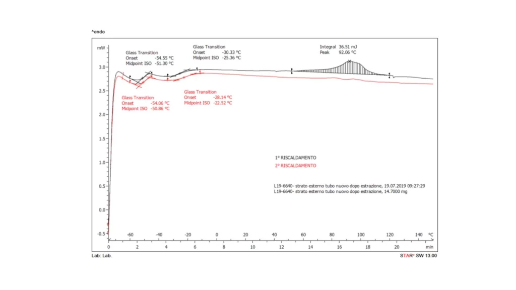
The outer portion of the new sample was analyzed before and after extraction treatment in organic solvent (mixture 50% acetone, 50% n-hexane).
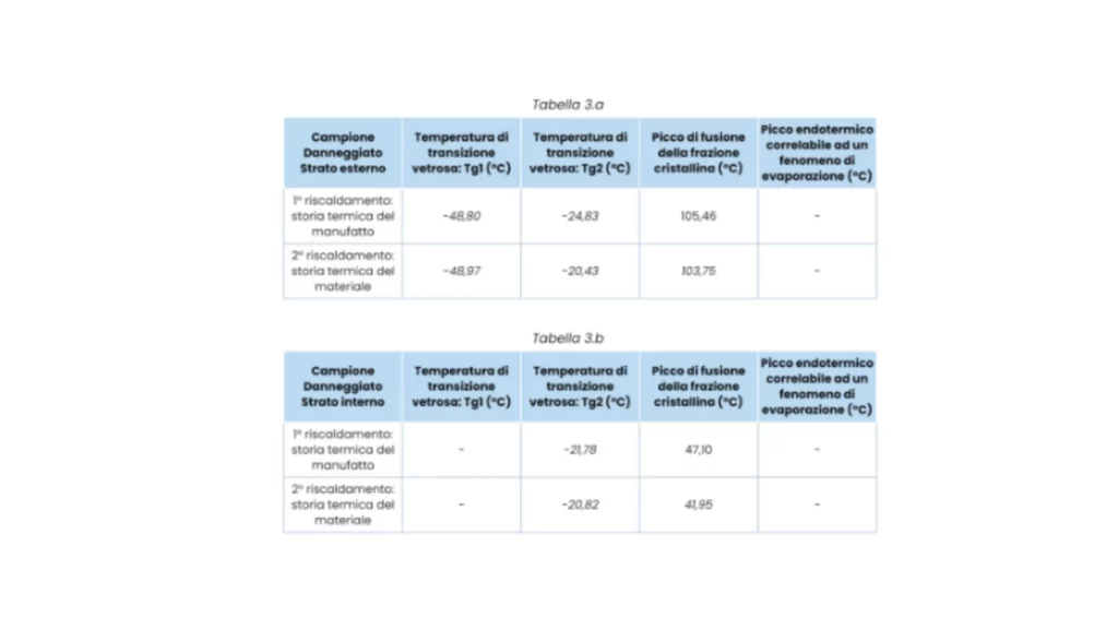
The obtained DSC thermograms (1st and 2nd heating) are shown in the following figures. The resulting information is shown in the tables opposite.
Note: DSC thermal analysis allows the determination of typical thermal parameters for polymeric materials, in this case rubbers. For this type of material, the characteristic thermal value is the glass transition temperature (Tg). From the results obtained, it is found that the hose consists of an inner layer of only nitrile rubber (NBR); while the outer layer is a blend of ethylene-propylene-diene rubber (EPDM) and NBR rubber. NBR rubber is characterized by poor weather resistance. For this reason it is blended with EPDM rubber, a more environmentally resistant elastomer.


5. Shore A hardness
Note 1: Shore A hardness measurements were performed by applying a waiting time of 3 seconds.
Note 2: The values are to be considered as indicative, as the shape and thickness of the samples do not comply with what is required by ASTM D2240:2015. The values obtained have comparative validity between the two tested artifacts, as they were obtained with the same operating methods.

6. Fluid resistance
A portion of the outer layer of the new hose was placed in contact with both gasoline and diesel fuel at room temperature for the duration of 24 h. Following the contact, both portions, compared with the new as arrived sample, show both a swelling effect of the rubber layers (more significant on the section in contact with gasoline) and a decrease in the Shore A hardness value of the outer layer. The average value of Shore A hardness found is given in Table 5. Figure 15 shows the cross-sections, both of the fuel-treated samples and a section of the new-as-arrived hose.
Note: The reference standards for evaluating fluid resistance are: ISO 1817 and ASTM D471. These standards refer to tests that are performed before and after contact with various fluids by the elastomeric material (rubber). These tests can be:
- change in Shore A hardness
- percentage change in mass
- percentage change in volume
- percentage change in tensile strength (load at break and elongation at break)
- change in tear strength
- Change in the surface appearance of the specimens. For example: appearance of cracks, bubbles, porosity, etc.
- Analysis of extracted substances by the fluid used
The criteria for acceptability of the results obtained, may be indicated by the client, or in some cases reference is made to standards, such as ASTM D2000. In the work performed, three fluids were chosen: commercial gasoline, commercial diesel fuel and a mixture of 50% acetone + 50% n-hexane. The objective is to verify whether after contact with each fluid the material is similar with what is found in operation. The first two fluids (gasoline and diesel fuel) would be those with which the pipe would come into contact in operation.


Discussion
From the analyses performed, the outer layer of both hoses consists of a blend of ethylene-propylene-diene rubber (EPDM) and nitrile rubber (NBR), while the inner layer would be found to consist of only nitrile rubber (NBR). These results would confirm the chemical composition of the rubber layers as indicated on the data sheet provided by the contractor. From the comparison analyses between the two hoses (damaged and new), the following significant differences are found:
- Macrographic and micrographic observations of the damaged specimen show the presence of integrity defects (cracks) only on the outer side of the specimen. The inner layer appears to be intact.
- Thermogravimetric analysis (TGA) and FT-IR show a minor presence of the low molecular weight components (various additives, for example: plasticizer) in the damaged sample, particularly on the outer layer of the tube.
- DSC analyses show different Tg (glass transition temperature) values of the elastomeric fraction between the two samples analyzed. In particular, on the outer layer of the damaged hose, an increase in this value is observed, most significantly on that belonging to the EPDM rubber fraction. These results are in line with the increase in hardness (stiffening) of the damaged tube.
- Chemical compatibility tests carried out on the NEW component with gasoline and diesel fuel showed a completely different phenomenon from that observed on the damaged tube, while extraction with a 50% n-hexane-50% acetone mixture led to similar results (see Shore A hardness values and DSC thermal parameters). This mixture consists of 50% hydrocarbons. Hydrocarbons are apolar organic compounds capable of modifying and/or degrading EPDM rubber; while they do not cause serious effects on NBR rubber.
Conclusions
Based on the results obtained, it is believed that the phenomenon of damage suffered by the hose is compatible with a partial extraction of low molecular weight components, particularly plasticizers, by some substance not compatible primarily with EPDM rubber. Unfortunately, with the analytical techniques used, it was not possible to find any contaminants correlated with the observed phenomenon.
Compatibility analysis with diesel fuel and gasoline showed the opposite behavior to that found on the damaged pipe. Therefore, they are not held responsible for the phenomenon found.
Note: During investigations where the damage is attributable to contact with a particular fluid, if the contact substances are volatile, they cannot be traced. In these cases, as in the present investigation, possible simulants are chosen to see how the material properties change and to be able to compare with what actually happened.
Is your component damaged? Let’s find out together why
Request information